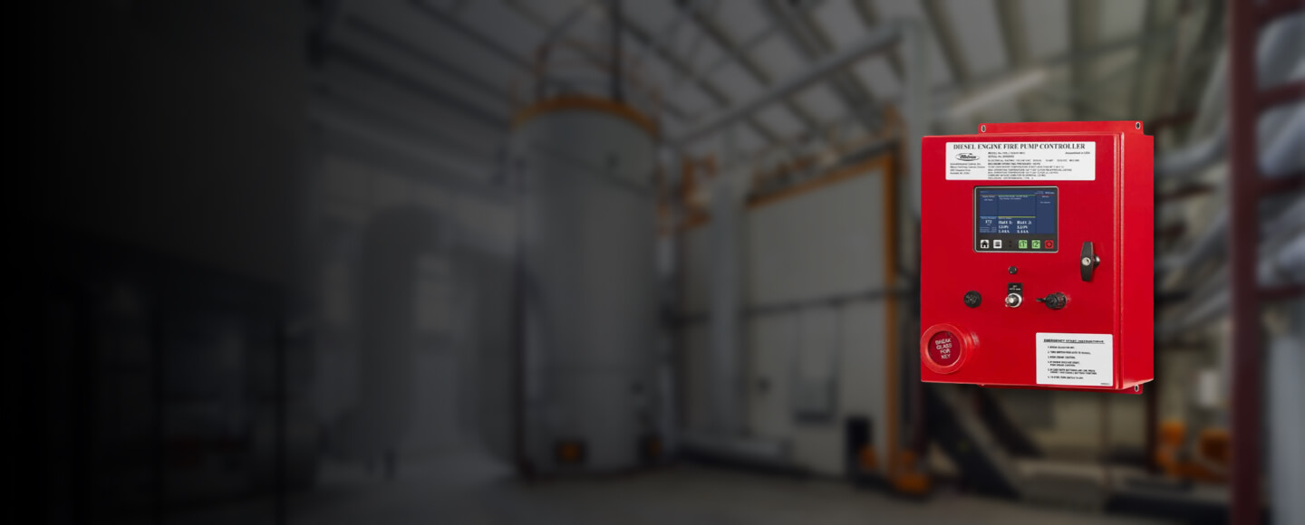
FD5 Microprocessor Diesel Engine Driven Fire Pump Controller
This controller is suitable for all engine types with either 'energized to run' or 'energize to stop' fuel solenoids.
Read More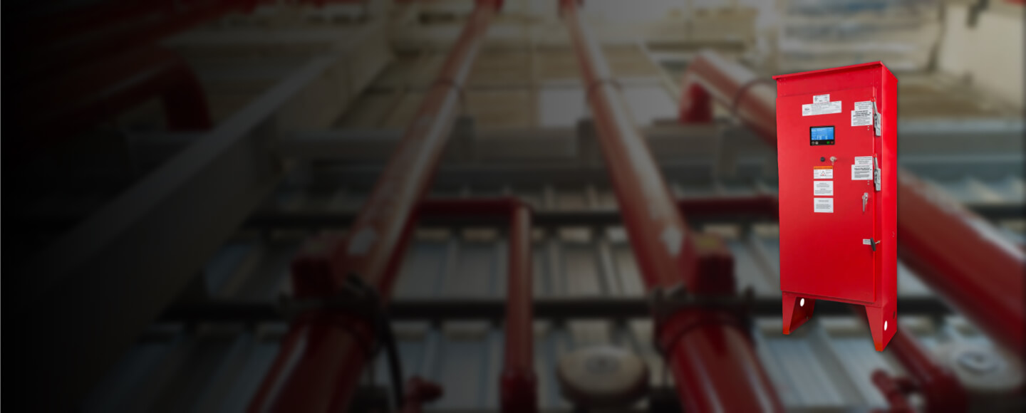
MPT Series Fire Pump Controllers
The Microprocessor based logic with real time/date clock capable of running 7+ years without AC power.
Read More